3 bit binary counter using d flip flop
Error (Forbidden)
This example is taken from T. Floyd, Digital FundamentalsFourth Edition, Macmillan Publishing,p.

Figure 18 shows a state diagram of a 3-bit binary counter. The circuit has no inputs other than the clock pulse and no outputs other than its internal state outputs are taken off each flip-flop in the counter.
The next state of the counter depends entirely on its present state, and the state transition occurs every time the clock pulse occurs. Figure 19 shows the sequences of count after each clock pulse. Once the sequential circuit is defined by the state utvi.indian stock market, the next step is to obtain the next-state table, which is derived from 3 bit binary counter using d flip flop state diagram in Figure 18 and is shown in Table Now we want to implement the counter design using JK flip-flops.

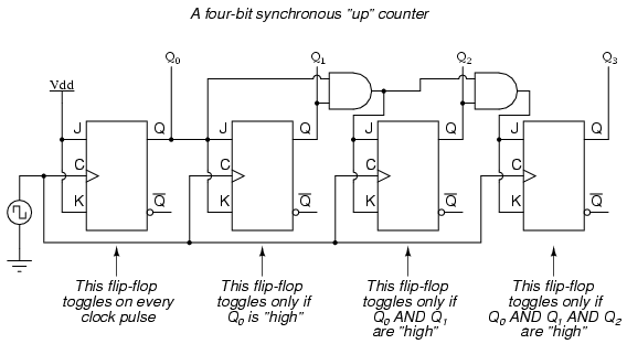
Next step is to develop an excitation table from the state table, which is shown in Table Output State Transitions 3 bit binary counter using d flip flop inputs. This is shown in Figure The 1s in the Karnaugh maps of Figure 20 are grouped with "don't cares" and the following expressions for the J and K inputs of each flip-flop are obtained: The final step is to implement the combinational logic from the equations and connect the flip-flops to form the sequential circuit.
Circuit Design of a 4-bit Binary Counter Using D Flip-flops – VLSIFacts
The complete logic of a 3-bit binary counter is shown in Figure Present State Q2 Q1 Q0. Next State Q2 Q1 Q0. Flip-flop inputs J2 K2.